6502 Single Board Computer Alarm System Photos.

The 6502 S.B.C. was constructed on a Vector wirewrap card with a 22 pin edge connector.
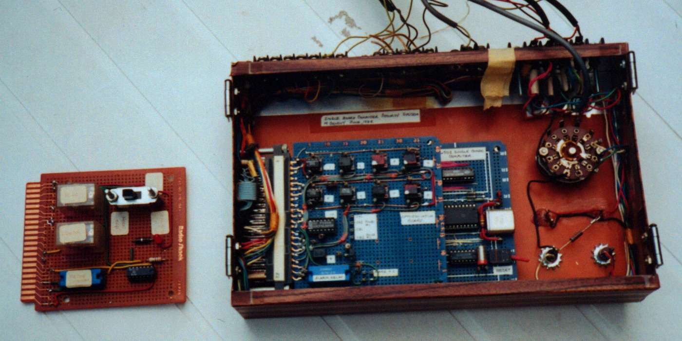
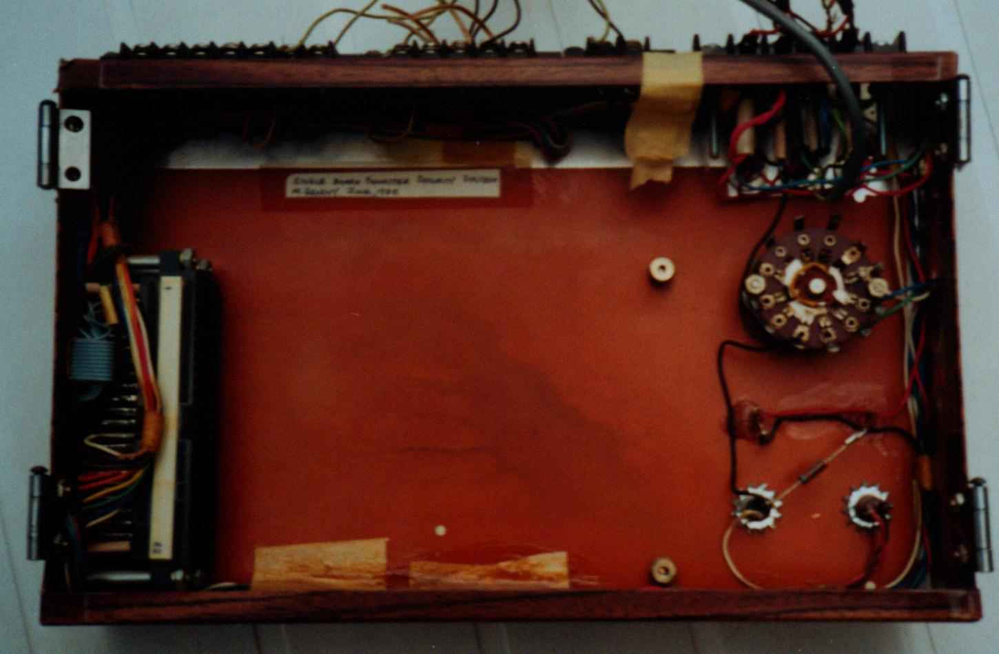
The 6502 S.B.C. and an optoisolator board were mounted inside a small panel. The optoisolator board was used to interface alarm switches to the SBC.
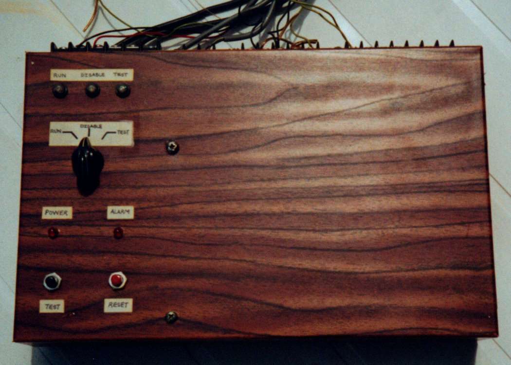
The front of the panel has a Control switch to select the mode of operation, an Alarm LED and Power LED indicator, and Reset and Test push buttons.
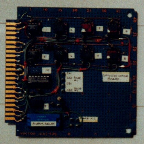
This is the optoisolator board which is used to interface alarm switches to the 6502 S.B.C. It also has an Alarm relay on it, and Watchdog Pulse outputs.
Both the 6502 and optoisolator board have 22 pin edge connectors. This made for easy removal of the cards to install the firmware Eprom.
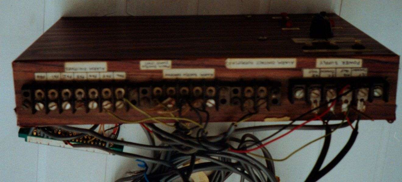
Barrier terminal strips at the top of the panel are used to connect the alarm switches and alarm horn. The unit is powered with 5 Vdc and 12 Vdc. The 5 Vdc is for the 6502 S.B.C. and the 12 Vdc is for the Alarm switches.
